BreakerBot:
A Semi-Autonomous Robot to Replace Circuit Breakers in Power Substations
Winner of the 2016 Best Senior Design Project Award from the Department of Electrical and Computer Engineering at BU
Honorable Mention for the 2016 Intel-Cornell Cup

Problem Statement
All over the world, power substations utilize circuit breakers to protect their customers from current overloads and short circuits. Replacing these circuit breakers for maintenance or testing is both dangerous, because of the risk of an arc flash, and tedious, due to the weight and geometry of these circuit breakers.
Consolidated Edison (ConEd) approached Boston University to design an automated process to replace circuit breakers in their power substations. An interdisciplinary team of mechanical, electrical, and computer engineering seniors developed a solution and manufactured a prototype for the problem. This prototype serves as a proof of concept, which will be scaled up in future phases of this project. Alignment algorithms, as well as the general procedure of inserting and removing circuit breakers will be demonstrated.
Solution
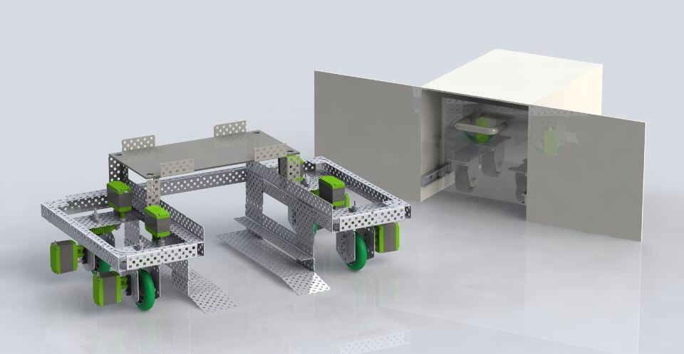
Our solution took the form a Wheeled Mobile Robot (WMR). A scaled prototype was constructed to demonstrate the following critical functionalities:
Alignment to the cubicle
Extraction and insertion the breaker into the cubicle
The critical load bearing aspects of the project will be assessed in further phases of the project. Budget and time constraints limited the scope of this project phase to demonstrating these critical functions.
Video of Alignment and Extraction
Design and Fabrication of Prototype
Critical Functions
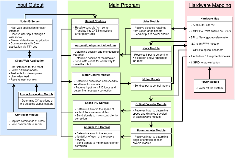
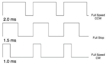
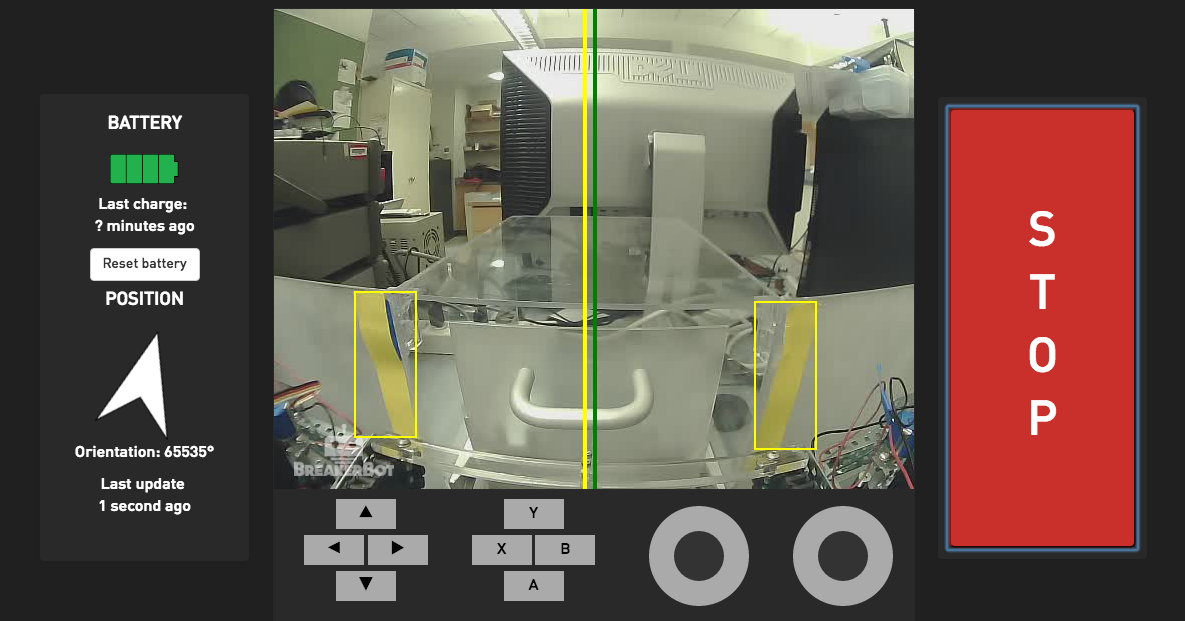
Alignment: The alignment functionality was achieved using a USB webcam with image processing on colored strips of tape as well as the onboard gyro. The image processing allowed for lateral and longitudinal alignment, and the gyro allowed for angular alignment. To execute the auto-alignment procedure, you must manually position the robot in the vicinity of the breaker cubicle such that the yellow markers are within view of the camera. Then simply engage the auto-alignment mode, and the robot adjust its angle and position until it is aligned. Once this is complete, you may move the arm to either remove or insert a breaker from/to the cubicle.
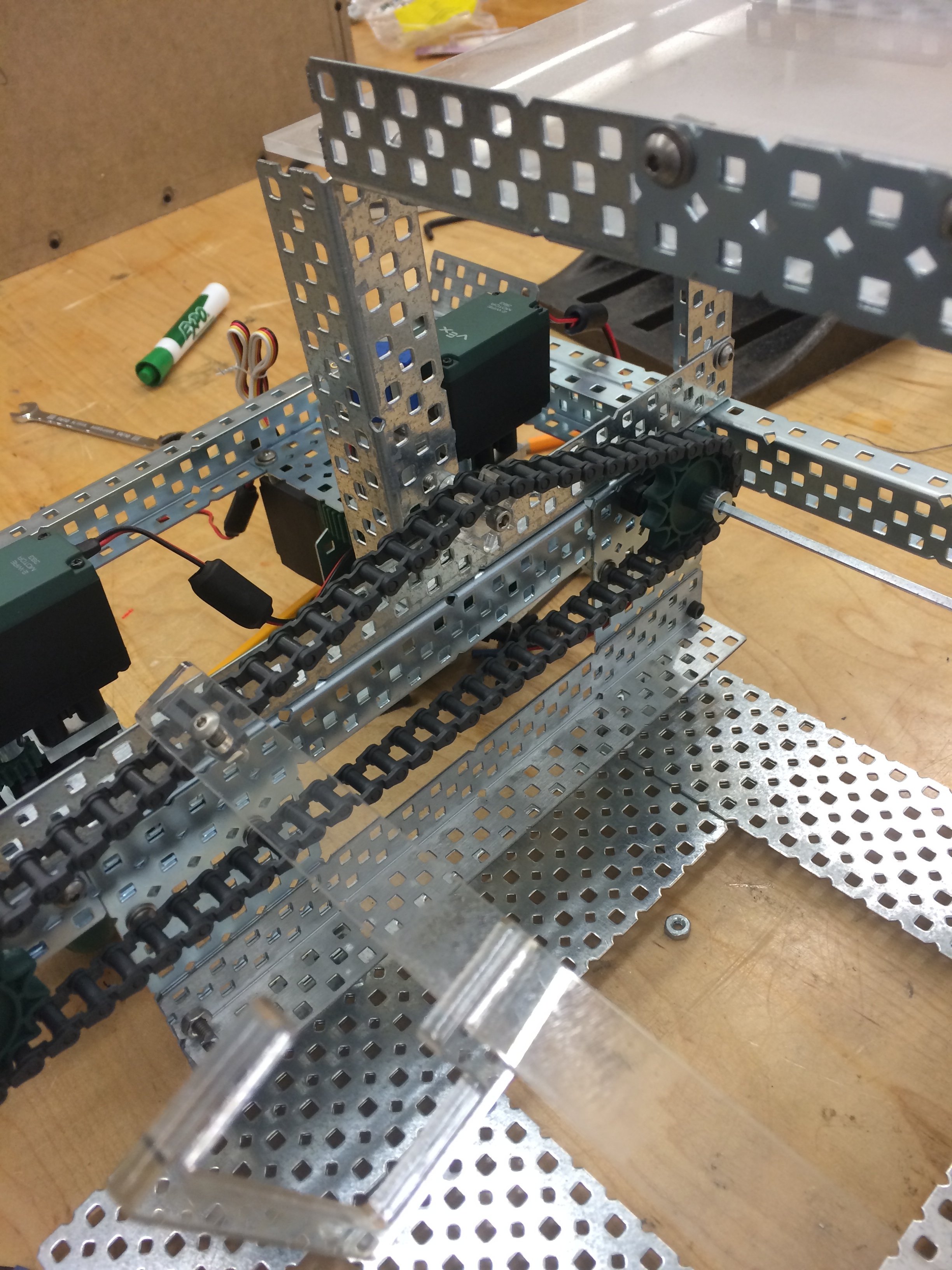
Extraction and insertion of the breaker: Because there are many different types of breakers in ConEd's electrical substations, it was difficult to make a robot that could be compatible with each breaker, as the locations of handles and other features on the breaker varied depending on the manufacturer. We decided to use an arm with a hook to latch onto the handle, as some breakers have a safety lever on the handle that needs to be depressed to release the breaker. Our scaled design does not include a mechanism to squeeze this safety lever, but we envisioned a pneumatic inflatable bladder on the hook could be used to depress the lever. A chain drive was selected to move the hook for the scale model out of simplicity. This will likely be changed in the full scale design, as chains do not perform well in a pushing configuration for inserting the breaker.
Project Management Choices
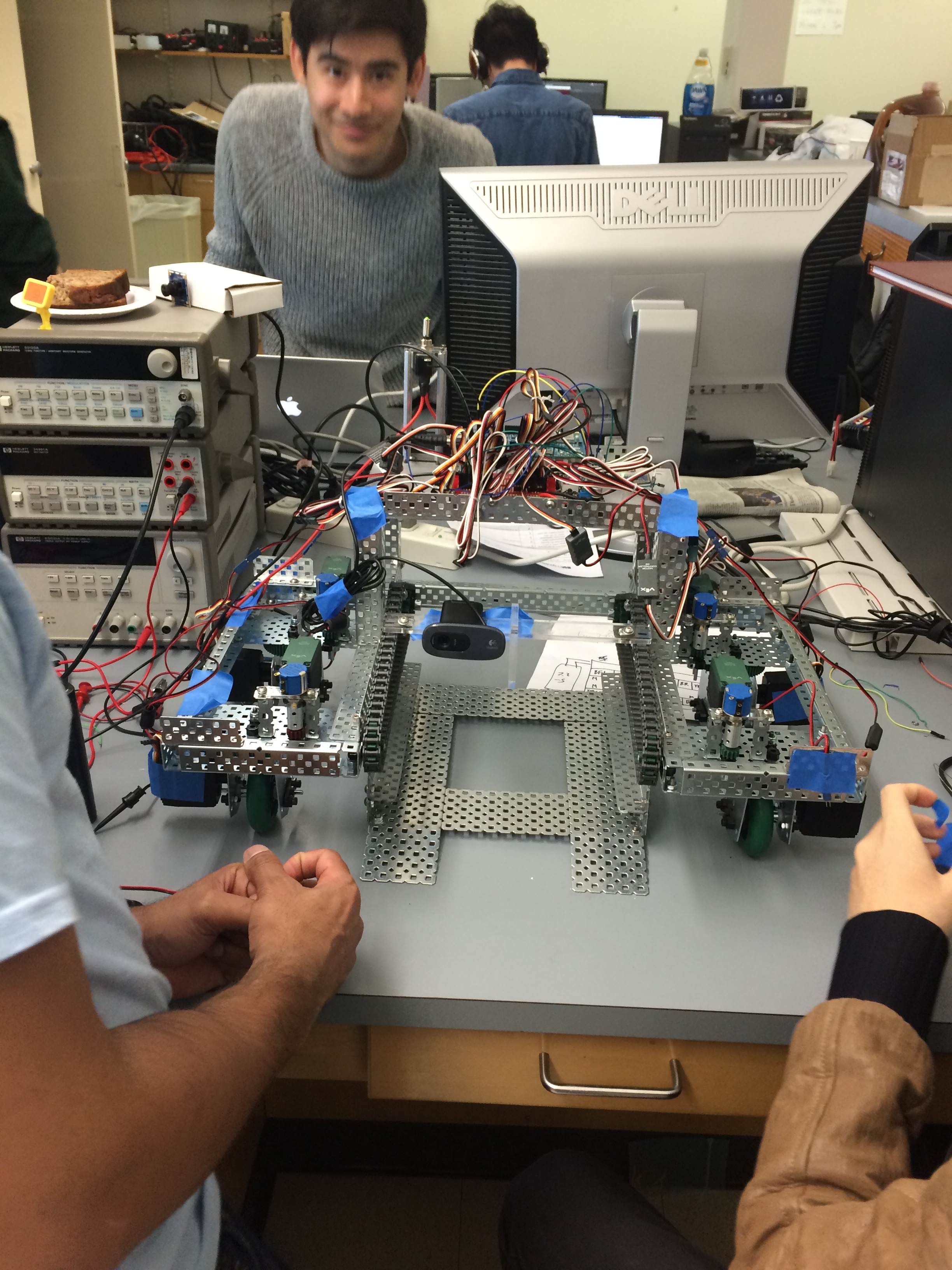
The chassis of the robot was constructed primarily using Vex Robotics hardware components. We selected this method over the more conventional method of designing and manufacturing chassis parts from scratch because we wanted the freedom to iterate and alter our design with ease. Many the concepts we needed test could not be reliably verified using a calculation or computer model, which necessitated the ability to rapidly make design changes. Rather than do all the design first and build at the end, we decided that we needed to quickly design, build, and test each system in succession in order to maximize our success. We designed the systems independently to ensure that the failure of one system would not result in the failure of the entire project.
The reduced scale of the project also greatly enabled the rapid iteration of ideas. With a full scale robot, many of the components would require a thorough load bearing analysis, and would then have to be manufactured on a CNC machine. However on this small scale, parts required no load analysis and could be quickly produced by a laser cutter in a matter of minutes.
As the first pieces of hardware were completed, the electrical and computer engineers could begin testing and verifying their systems. Near the end of the project, most of the time was spent in systems integration to enable all of the previously tested subsystems work together. Many smaller housings and mounts had to be constructed for the electronics, which was simple because the bulk of the mechanical work was completed.
Overall, we were very pleased with the way this project turned out. We were able to deal with setbacks and design changes very fluidly due to the way we had structured our project. The next phases of the project will hopefully aim to refine some of the control algorithms of the robot, and begin scaling the robot to actual size. This will require the original design of a swerve module capable of supporting over half a ton, which we suspect will be the next primary mechanical design problem.