Introduction
This semester I am taking an aircraft design and performance class. The term project is to complete a conceptual aircraft design - each group will be designing a different type of aircraft. Our group is designing an MSA, or Maritime Surveillance Aircraft. The purpose of this aircraft is to loiter for long periods of time at low altitudes to observe/monitor maritime vessels, act as an airborne control center for nearby aircraft, and even deliver payloads (sonobuoys) and ordnance (torpedoes, air-surface missiles). Our professor provided us with Excel spreadsheets that have many of the calculations programmed into them; our goal is to optimize the parameters to meet the requirements. We also need to produce a 3-D model of our design. This is where the Excel sheets lack in ability. They provide very rudimentary 3-views of the aircraft. I decided to use MATLAB to take the results from the Excel spreadsheet and produce coordinates for a wireframe model of the airplane, which could be loaded into CAD software and turned into a 3-D model.
Currently, my MATLAB program can only produce the wireframe of a wing (or any similar aerodynamic surface). I am actively working on expanding it to create fuselage cross sections which will be used to create a 3-D model.
Design
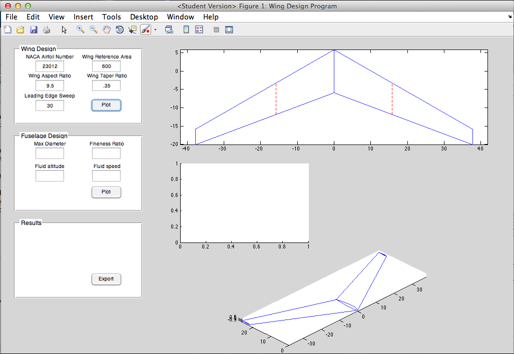
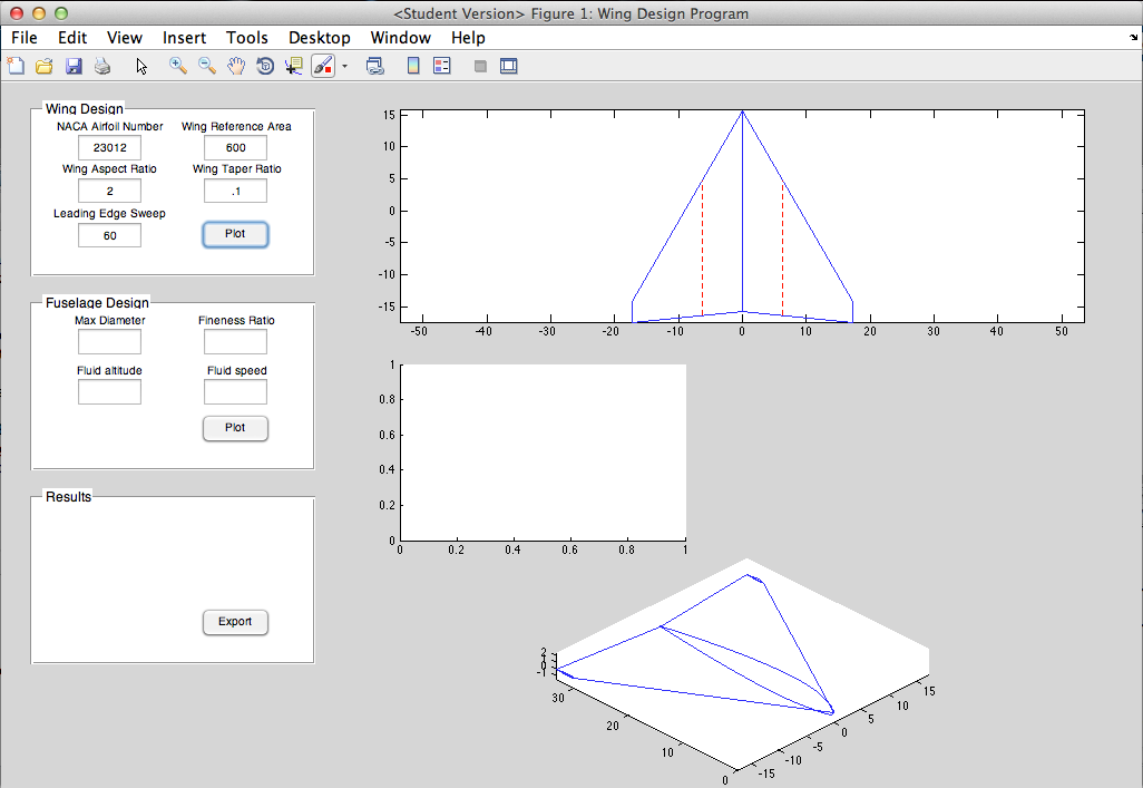
I adapted this program for one I previously made for an aerodynamics class. The inputs were reversed - for that class, the area needed to be calculated for a given wingspan, whereas in the design scenario the wingspan is determined by the area and the aspect ratio, so the inputs needed to be changed. I also added the capability to sweep the wing. I also added the a section on the planform view to show the MAC - this is an important thing to visualize. The 'Export' button creates .txt files with the tip and root airfoil coordinates. These can be loaded into SolidWorks or any other CAD program as a curve, and the tip and root curves can be lofted together into a solid wing. Then the wing is simply mirrored about the root to create the other half and complete the wing.
Capabilities
Plot any 4-digit or 5-digit airfoil (uses my airfoil generator function). Create basic trapezoidal aerodynamic surfaces with airfoil cross sections. Wing twist or washout, and angle of incidence (not visible in GUI yet). Parameters include NACA airfoil, wing reference area, aspect ratio, taper ratio, and LE sweep. Plots MAC and spanwise location of MAC. Export coordinates of root and tip airfoils to create a 3-D model in CAD software.
Improvements
The current method in which the wing is swept is inaccurate, as it 'drags' the tip rearwards (or forwards) to achieve the required leading edge sweep. However the wing should really be rotated such that the airfoils are no longer parallel to the airstream; this is what makes a swept wing effective. Rotating is difficult though, because then you have to account for the fact that tip and the root will be at the incorrect angle, and you have to adjust for that. This is okay to make a model for viewing/aesthetics, but I should look into updating this in the future. I should also plot points on the quarter chord MAC as this is another important location. I will continue working on this GUI to add fuselage plotting capability. Also the wing washout/twist/angle of incidence parameters can only be accessed from within the code; I need to make boxes on the interface to change these parameters.


