How to Weigh Your Head: Pt. 1

Background

During my time at Boston University, I was a Teaching Assistant for the Product Design course required for all mechanical engineering majors. In contrast to our other engineering courses which taught scientific principles, this course focused on exposing students to structured ideation methods, materials/design selection, functional analysis and decomposition, and how to generate effective engineering problem statements.

The Question

The professor, Greg Blonder, posed a question to the class during one lecture as an exercise:

How could you determine the weight of someone’s head, without removing it?

This question seemed underwhelming at first, but the as the groups discussed their ideas, they began to realize a solution was not trivial. Their solutions roughly fell into two categories:

  1. F = ma, f = (k/m)^(1/2)

    These involved resting the person’s head on a scale or measuring acceleration response to a known force. The main problems with these approaches are that one must make many assumptions for the reaction forces and moments/damping ratios/spring rates in a person’s neck. Additionally, some of these procedures may be harmful/intrusive to the subject, as they involved vibrating the subject by their neck, whacking their head with an instrumented hammer, rapidly rotating the subject, and administering muscle relaxants to the neck muscles. However depending on your definition of success, these could be interpreted as viable solutions. The question was open ended…

  2. Fluid Displacement/Buoyancy

    These methods generally involved submerging a person in water up to their neck, or holding them upside down so only their head is underwater. All of these methods fall victim to the common fallacy that buoyant force informs the weight/mass of the submerged object. This is of course not true; the buoyant force is simply equal to the weight of the water displaced and does not depend on the mass of the submerged object. The displacement measurement from this method informs the volume of the head, and combined with density one can obtain mass. However one must either devise a way to measure the average density of someone’s head, or make an assumption. Again depending on the definition of success, assuming the average density and simply measuring volume could be a viable solution for someone’s application.

When the professor revealed his solution, it became clear that class had overlooked one key idea: remote sensing. With remote sensing techniques, it is possible to measure properties of matter without making physical contact. These technologies work by analyzing the EM or acoustic signals propagated by the test article to inform its properties. This problem is in a way already solved by the various medical imaging technologies such as CT scans, MRI, and ultrasound. Once the subject is scanned, the only remaining question is debating where the head ends and the neck begins. But I believe that is outside the scope of this exercise.

Professor Blonder stated that it would be theoretically possible to apply the principles of remote sensing/medical scanners to a more practical, ‘backyard’ solution. His solution, informed by the principles of CT scanning, was to ‘scan’ the subject by placing them on a balance beam at various positions w.r.t the fulcrum, and recording the mass of the weight required to balance the beam at each position. The resulting system of equations could be solved to determine a mass per length vs. length profile of the subject, and by integrating/summing over the length corresponding to the location of the head, the mass of the head may be determined. This is as much detail as he gave. He also stated that one could perform multiple scans at various angles and transform the data into an 2D density map. This is of course the working principle of a CT scanner.

The Project

I found myself still thinking about this exercise years after graduating, and decided to try and pick up where the professor left off. The goal of this project is to assess the feasibility of the method described above for determining the mass of a person’s head. I’ve done some preliminary research on this topic (mostly reading about the principles of Computed Tomography and writing way too many mass balance equations) and have identified some key objectives/stepping stones:

  1. Solving the System of Equations for a Single Scan

    This method begins by modeling the human body as a rectangle divided into n equally sized slices of uniform density. Because the density of each slice is uniform, its CG is at it’s midpoint, thus the CG location for each slice is known. The mass/density of each slice is still unknown. This model makes sense if you imagine the limiting case as n approaches infinity; the slices are so thin that their density will essentially be uniform. The ‘body’ is then placed on the balance beam at a known position and a known mass is added to the opposite side at a known position to balance the moments. Summing the moments on each side of the beam, we obtain an equation with n unknowns (the masses of each slice). Thus if you repeat this measurement n times at n unique positions, we end up with a system of n equations with n unknowns. So it seems the problem is solved.

    However upon further thought, I recalled my linear algebra professor’s musings on linear independence and matrix invertability. Reexamining the model, it occurred to me that the equations generated may all be linearly dependent, as the initial equation is just shifted incrementally to create the subsequent equations. The first task will be to determine whether or not this is true. If the equations are linearly dependent, then the matrix cannot be inverted, and Ax = b cannot be solved. Based on a simple hand calc, the method works for a 2x2 matrix, but I’m not sure about larger matrices. Looks like I will have to dust off my linear algebra textbook.

  2. Applying the Inverse Radon Transform to Produce an Image

    Assuming the matrix is invertible and the system of equations can be solved, I will write a Matlab or Python script to scan a virtual object at various angles using the scan method developed in objective #1. These scans will then be lined up to construct a sinogram. Each scan represents one column of a sinogram. The Inverse Radon Transform (IRT) will then applied to the sinogram to obtain an image. A filter must be applied in fourier image space to compensate for the center of the image being oversampled.

    I am fairly certain most image processing libraries will have built in functions for the IRT and fourier image space filtering, but I’m not sure about a function to assemble a sinogram from a series of data from multiple scans. I may have to write that function myself.

  3. Evaluating the Success of the Solution

    Lastly, I will attempt to estimate uncertainties for a theoretical measurement device, and calculate the theoretical resolution and accuracy of the device.

    Off the top of my head, some of the sources of uncertainty/error will be friction in the fulcrum, position measurement of the body and the balance masses, mass measurement of the balance masses, nonuniform density of the beam and the balance masses, movement of the subject (especially during multiple scans at various angles), and scan angle measurement. There will also be errors from the IRT and image space filter but I’m not yet sure how to quantify those. I suspect it will be quite challenging to figure out how to propagate the base uncertainties of mass and position all the way through the IRT and filtering steps.

    Assuming I’m able to propagate these uncertainties, I will also try to calculate the resolution of such a device by propagating the resolutions of various COTS methods for measuring position and mass. This will let us evaluate the success of this solution and allow for comparison to other solutions.

Stay tuned! More to follow.

MATLAB Project: Membrane Vibration

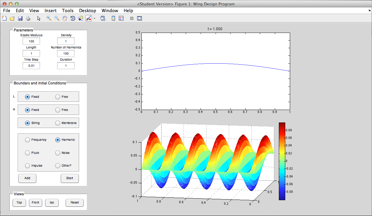
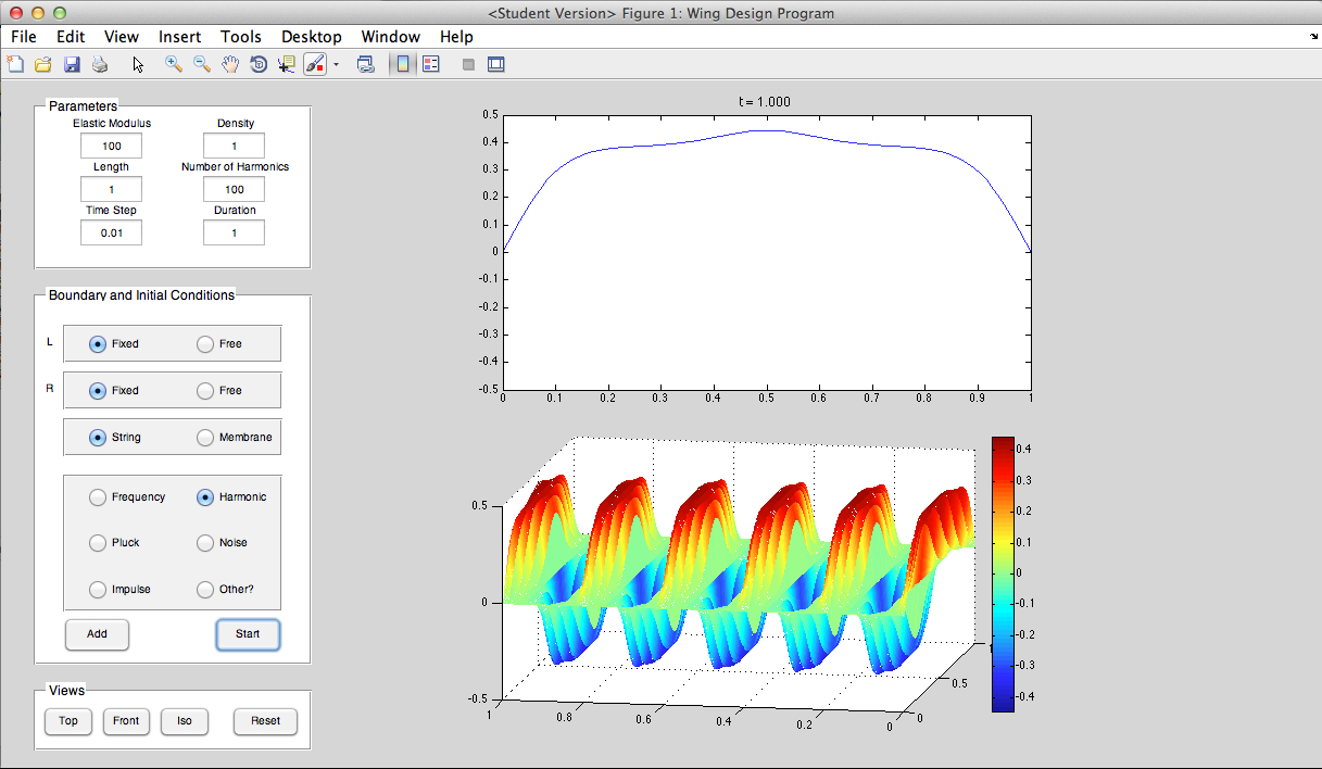
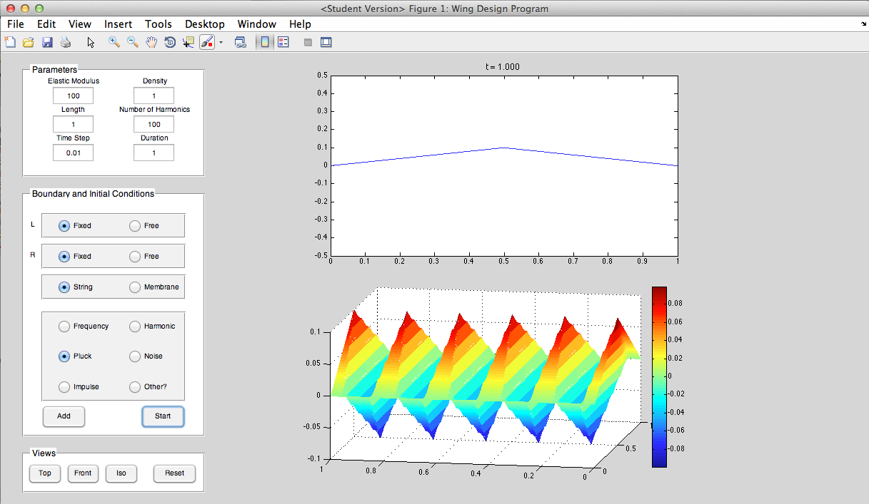
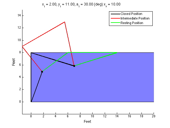
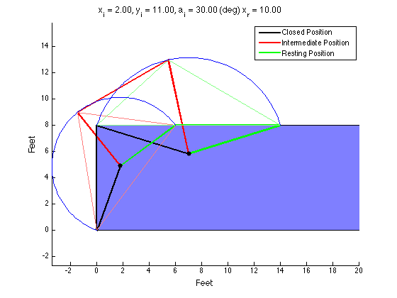
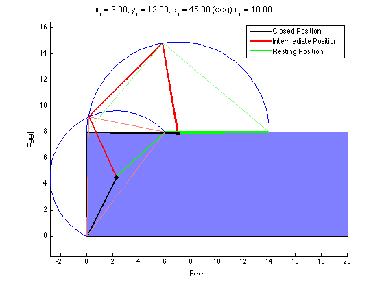
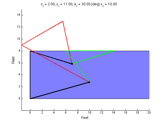
I was able to get the membrane vibration to work for a rectangular membrane. The equations are quite different for a circular membrane, so I'll need to write a new function for that. I'm still working on implementing this function into the GUI.
Fundamental Mode


p = 1, q =2


p = 2, q =2


p = 4, q =2


p = 3, q =3

Bike Brake Light: Part 1

I've been thinking a lot about developing a brake light for a bicycle. The need for such a device has always been obvious to me, but for those of you who may think otherwise, let me explain. Cyclists communicate with drivers and other road users primarily using hand signals. So if you are stopping, you have to let go with one hand and signal. However, if you are doing an emergency stop, it is both difficult and unsafe to signal - both hands need to be on the handlebars to control the bike during an emergency stop. Unfortunately, that's also the most important time when those behind you need to know you're stopping. The situation is essentially a catch-22: if you need to stop quickly, then you should signal to those behind you; but if you signal to those behind you, you won't be able to stop quickly.
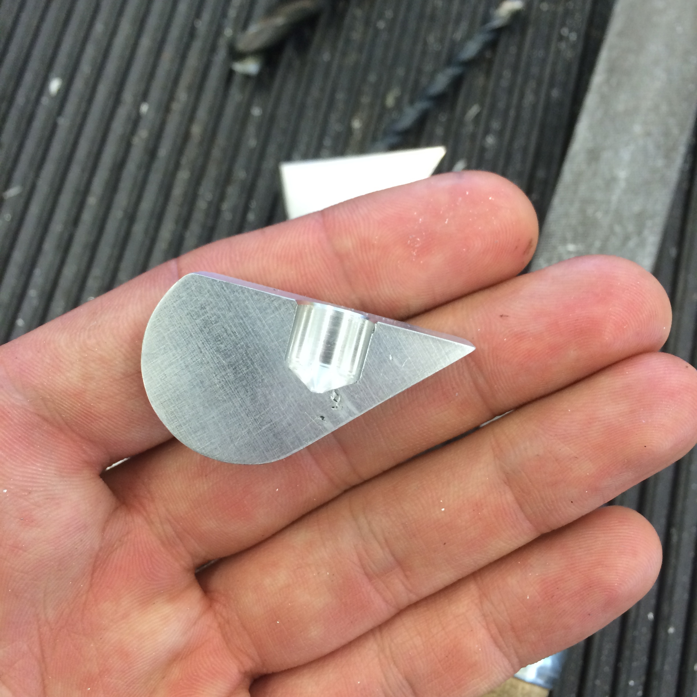
In my mind, a brake light is the most effective way for cyclists to signal to other road users. But this isn't a new idea, and this certainly won't be the first to come to fruition. So why don't we see any bikes with brake lights now? From the bike lights I have seen online, there seem to be a few problems with current bike brake lights:

  1. Can't properly sense braking
    This mainly applies to those brake lights that use accelerometers to detect the braking. Accelerometers tend to misinterpret bumps and other vibrations as brake applications, causing erroneous lights.

  2. Incompatible with certain types of bikes
    Other brake lights use a separate mechanical switch that connects to the caliper or the cable. These may not fit all bikes. Also, they are susceptible to all the wires and the wear and tear of a separate mechanical switch.

  3. Not bright enough
    Some of the bike brake lights have only 1-2 small, low power LEDs. What is the use of a brake light if no one can see it?

  4. Concern that other users won't understand the signal
    This is the only issue that cannot be solved directly with the device. Perhaps some experiments can be done to test brake lights on unsuspecting motorists/cyclists and see if they understand what the signal means in time to brake. This could end badly...

I will attempt to create a bicycle brake light that solves these problems. Right now I am leaning towards an improved accelerometer sensing brake, that may incorporate another sensor to improve the accuracy of identifying braking periods. But I will also investigate other methods for activating the brake light. Who knows; maybe I'll find some elegant and unobtrusive way to mount a mechanical switch to trigger the brake.